Stoplog consists of several sets of horizontal beams/logs stacked vertically. For narrow openings, the logs span between support slots at the ends of the openings. For wide openings, intermediate removable support posts may be required. They are prevalent in the past because of its low establishment cost, simple erection and easy operation.
Should the same freeboard be maintained along a channel?
The freeboard is defined as the vertical distance from water surface to the top of channel bank. The selection of freeboard is dependent on the consequence should overflow out of channel bank occurs. Other than that,consideration should also be given to prevent waves, superelevation and fluctuations in water surface from overflowing the channel banks.
What is the difference between on-seating and off-seating head in penstock?
A penstock is commonly used to control the flow and water level and for isolation of fluid. It mainly consists of a sliding door which is controlled by mechanical spindle moving through a hole in a frame built onto a structure. Penstock is the term used in UK while sluice gate is more commonly adopted outside UK. In the design of penstock, it is important to identify if it would take on-seating head or off-seating head.
During the time of construction, cracks are likely to develop in small diameter concrete pipes. Why?
During the construction of new pavement, vibratory roller and heavy equipment are needed to compact the filling material and bituminous material. These heavy equipment could generate very high impact load with short duration on the concrete pipes.
What is the importance of uniform support for precast concrete pipes?
Concrete pipes are designed to be uniformly supported along the length to carry vertical loads on its top. They are normally not intended to serve as a beam to carry loads in longitudinal direction under poor ground supports (i.e. high and low spots in bedding).
Closed Box Trough And Overhang Aqueduct
An aqueduct is a structure carries canal water through it and crosses over a natural drainage river or nallah. An aqueduct is provided when canal bed level is higher than HFL of natural drainage.
In case of open through aqueduct the service road is discontinuous, and during rainy season for inspection of aqueduct site engineer has pass through submersible causeway to downstream side aqueduct. In this case cost of aqueduct and cost of the causeway and service road is to be borne by irrigation department. But during heavy flood the water flow over cause way and it can not be possible to inspect aqueduct for throughout length. Hence closed box aqueduct is proposed in place of existing open trough aqueduct.
Hydroelectric Power Generation
The electrical power obtained from conversion of potential and kinetic energy of water is called Hydroelectric power
PE=WZ
where
PE= potential energy
W =total weight of the water
Z =vertical distance water can fall
Power is the rate at which energy is produced or utilized:
Read More
Venturimeter Flow Computations
Flow through a venturimeter is given by
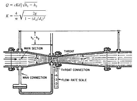
where
Q= flow rate, ft3/s (m3/s)
c =empirical discharge coefficient dependent on throat velocity and diameter
d1= diameter of main section, ft (m)
d2= diameter of throat, ft (m)
h1= pressure in main section, ft (m) of water
h2= pressure in throat section, ft (m) of water
Economical Sizing
ECONOMICAL SIZING OF DISTRIBUTION PIPING.
An equation for the most economical pipe diameter for a distribution system for water is
D=0.215*(fbQ3aS/aiHa)1/7
where
D= pipe diameter, ft (m)
f =Darcy–Weisbach friction factor
b =value of power, $/hp per year ($/kW per year)
Qa= average discharge, ft3/s (m3/s)
S =allowable unit stress in pipe, lb/in2 (MPa)
a= in-place cost of pipe, $/lb ($/kg)
i =yearly fixed charges for pipeline (expressed as a fraction of total capital cost)
Ha =average head on pipe, ft (m)
Flow From Wells
The steady flow rate Q can be found for a gravity well by using the Dupuit formula:
Q =[1.36K(H 2-h 2)]/log(D/d)
where
Q =flow, gal/day (liter/day)
K= hydraulic conductivity, ft/day (m/day), under
1:1 hydraulic gradient
H= total depth of water from bottom of well to free-water surface before pumping, ft (m)
h= H minus drawdown, ft (m)
D= diameter of circle of influence, ft (m)
d =diameter of well, ft (m)
The steady flow, gal/day (liter/day), from an artesian well is given by
Q=[2.73Kt(H -h)]/log(D/d)
where
t = thickness of confined aquifer, ft (m).