

Abstract
This paper discussed the design of substructure of bridge subjected to load of train with using two codes, the first code is AASHTO code and the second is the Chinese Code. This study focuses on the substructure of the bridge design and the design manually with the two codes.
By the design of the Bridge using the codes above, we found that Chinese Code is more safely that the number of reinforcement bars more in the pile cap and pile.
Settlement of the bridge also is calculated by using the data collected from the project site, the vertical ultimate bearing capacity of pile group and the dynamic action of the train loads, by this study it can be concluded all the above are safe values.
Another analysis by using the three-dimensional Plaxis program of finite elements and many parameters calculated, the value of the maximum vertical displacement was near from the calculated value which gives another checking for the design and maintain the safe conditions for the Bridge.
1. Introduction
Many of codes used in the world for design the bridges and many of countries have special codes for design depending on the specialty of that country and the nature, environmental conditions, effect of earth quakes etc. In the United States Bridge Engineers use AASHTO’s standard Specification for Highway Bridges and, in similar fashion or trends, German bridge engineer utilize the DIN standard and British use the BS 5400 code. In general, countries like German and United Kingdom which have developed and maintained major highway systems for a great many years possess their own national bridge standards. The AASHTO Standard Specification, however, have been accepted by many countries as the general code by which bridges should be designed.
In this paper, the design of a bridge by using two codes the AASHTO and Chinese codes. The AASHTO Code for design bridges named “American Association of State Highway and Transportation
Officials.”
In China there are many codes for design about 81 codes for design for all the majors in the civil engineering with serial numbers of standard, the code used for this study is (The Chinese National Standard (CNS, 2002)) [4], Building Foundation Design Code (GB50007-2002). The Chinese Codes for design bridges focusing on the rail-way design like:
– Fundamental Code for Design on Railway Bridge and Culvert (TB10002.1-2005).
– Code for Design of Steel Structure of Railway Bridge (TB10002.2-2005).
– Code for Design on Reinforced and Pre-stressed Concrete Structure of Railway Bridge and Culvert (TB10002.3-2005).
– Code for Design on Concrete and Block Masonry Structure of Railway Bridge and Culvert (TB10002.4-2005).
– Code for Design on Subsoil and Foundation of Railway Bridge and Culvert (TB10002.5-2005).
– Standard for Constructional Quality Acceptance of Railway Bridge and Culvert Engineering
(TB10415-2003).
2. Research Significance
This paper is to make a comparison between two or more codes in different countries to show the differences and similarities and advantages and disadvantages also for checking the design by the analysis and find the suitability of using the structure according to the design.
3. Design with Two Codes
By using the manually procedure steps of calculating the design of the bridge through the data provided from a project and applying the standards loading as following:
Design load: dead-weight of the 32 meter simply supported beam is 7862.88kN. Secondary-dead load
is 3.792MN.
Lateral swaying force of train, seismic force and the other horizontal load are taken into consideration,
so 12% of the vertical load is considered as horizontal load in the calculation.
Total horizontal load = 0.12 × (7862.88 + 3792)
= 1398.585kN
Total vertical dead load = 7862.88 + 3792
= 11654.88kN
Live load from the superstructure according to Chinese Code:
Maximum = 220kN
Minimum = 92.0kN
By taking the same dimensions and loading but using the two codes above, it can be shown in Table 1, the design with the two codes is different in some parts of the bridge and similar in the other, that the safety of Chinese Code is more than of AASHTO Code.
Table 1: Comparison of design bridge by using two codes (similarities and differences)
|
Footing design |
AASHTO Code |
Chinese Code |
|
Dimensions |
(5×6)m, thickness = 1.5m |
(5×6)m, thickness = 1.5m |
|
Number of piles |
4-bored piles with Dia. = 1m, with depth = 62.7m |
4-bored piles with Dia. =1m, with depth = 62.7m |
|
Pile cap design |
25 bars #9 (2.8cm) in the bottom mats
|
Number of bars = 29 bars (2.8cm) in each direction in the bottom mats |
|
21 bars #9 (2.8cm) in the top mats |
Number of bars = 25 bars (2.8cm) in each direction in the top mats |
|
|
Pile design |
16 bars #8 (2.5cm) in the bottom
|
Number of bars = 20 bars (2.5cm) in each direction in the bottom |
|
24 bars #8 (2.5cm) in the top |
Number of bars = 29 bars (2.8cm) in each direction in the top |
4. Settlement calculation and discussion
4.1 Settlement calculation
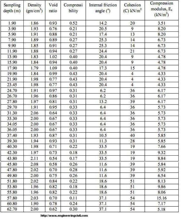
The settlement calculated of the Bridge due to the effect of loading by using the data provided from the soil investigations and testing in addition to the provided information from the design as following:
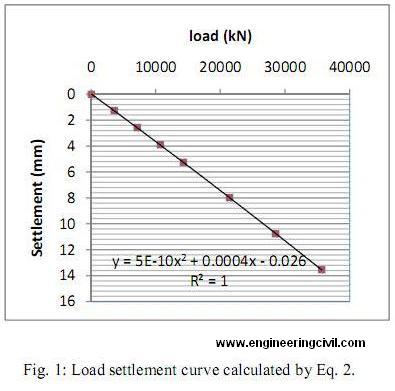
The dimension of the pile cap: (length = 6m, width = 5m, thickness = 1.5m) as shown in Fig. 1
The applied pressure: 100kPa, 200kPa, 300kPa, 400kPa, 600kPa, 800kPa, 1000kPa
The depth of the piles: 62.7m (according to the soil investigations reaching to the strong layer)
Effective depth for piles = 2/3× (62.7) = 41.8m (the depth of calculation of effective stresses)
The stress increase at the middle of each soil layer by the load Qg calculated in the following formula:
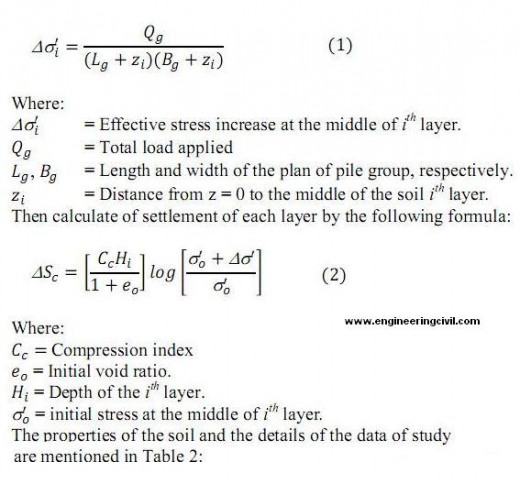
Table 2: Properties of the soil for all the depths of the layers
The model of the pile and pile caps of the designed bridge is shown in Fig. 2
Therefore, the /\S cis calculated for each layer of soil and each load as shown in table 2, and draw the relation between load and settlement curve as shown in Fig. 1.
As shown from Table 3 and Fig. 1 that the maximum value for the settlement equal to about 13.546mm at pressure 100kPa and this value within the permissible limit for the settlement compared with allowable settlement Skempton and McDonald (1956) limitations for maximum settlement and maximum angular distortion that means the foundation is safe and can bear the loading of the structure.
Table 3: The values of the pressure, load and settlement (AASHTOO)
|
P(kPa) |
Load (kN) |
Settlement (mm) |
|
0 |
0 |
0 |
|
100 |
3570 |
1.267 |
|
200 |
7140 |
2.576 |
|
300 |
10710 |
3.907 |
|
400 |
14280 |
5.256 |
|
600 |
21420 |
7.999 |
|
800 |
28560 |
10.773 |
|
1000 |
35700 |
13.546 |
4.2 Settlement Calculation in Chinese Code
The settlement of the pile group can be calculated from the following formula:
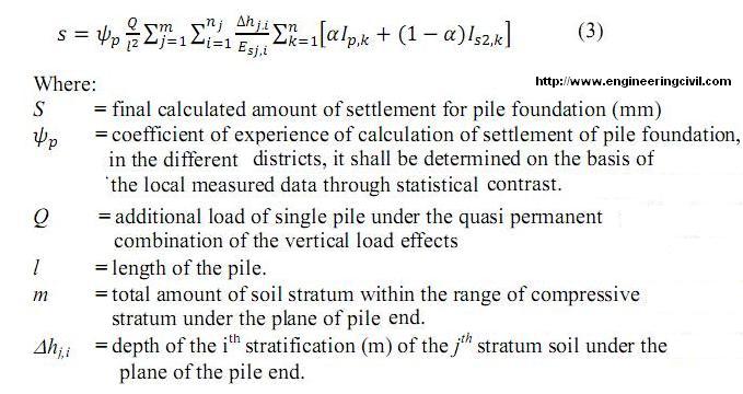
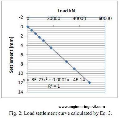
As shown from Table 4 and Fig. 2 that the maximum value for the settlement equal to about 11.973mm at pressure 1600kPa and this value within the permissible limit for the settlement compared with allowable settlement in the Chinese Code which equal to 15-20mm.
5. Vertical Ultimate Bearing Capacity of Pile Group
In order to determine the vertical ultimate bearing capacity of the pile group, a large uniform pressure was applied to the top of the pile. In the calculation, a pressure of 1000kPa was imposed, which is equivalent to a resultant force of 30000kN (5×6×1000). The calculation gives the load versus settlement curve for the mid-point on the long side of the upper pile cap, as shown in Figure 1. Figure 1 shows that there is an obvious turning point on the load-settlement curve. Before that turning point, the load-settlement curve is approximately linear. After the turning point, the settlement increases abruptly as the load increases, indicating a divergent trend, and the final settlement cannot approach to a stabilized value.
The Chinese Standard specifies key points for a single pile load test (CNS, 2002), which includes taking the load corresponding to the beginning of the steep drop on the measured load-settlement curve as the single pile bearing capacity. Applying this specification to the results of the numerical analysis on the pile group, the vertical ultimate bearing capacity of the pile group can be taken from the beginning of the steep drop on the calculated load-settlement curve.
From Figure 2, it can obtain the load corresponding to the steep drop point to be 1000kPa, which is converted to a resultant force of 30000kN, i.e., the vertical ultimate bearing capacity of the pile group and this value is larger than the total vertical loads.
We can calculate the ultimate load-bearing capacity of group piles from the following formula:
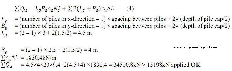
Therefore the value of the ultimate load-bearing capacity of group piles more than the applied load, indicating the bearing capacity of the pile group is sufficient.
For the Chinese code we can also use the following formula for a single pile.
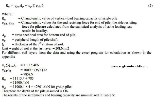
Table 5: Comparison of bridge design by using two codes (similarities and differences)
| Final settlement calculation for pressure = 1000kPa | 13.546mm (Eq. 2) | 7.483mm (Eq. 3) |
| Bearing capacity for group piles | 3455.8kN (Eq. 4) | 47601.6kN (Eq. 5) |
6. Action of Train Loading
The Railway has a design for speed of 350 km/h. The dynamic load of the high-speed train is transmitted to the bridge pier through rail track, track tie plates, and base plates and is transmitted to pile cap and pile foundation. To simplify the calculation, the load on the bottom of the track tie plates is assumed to act directly on the top of the pile cap and a pseudo-static method is used, which is considered conservative. The dynamic stress amplitude on the bottom of the track tie plates can be calculated as follows:
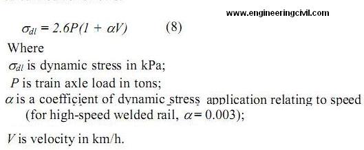
For the passenger cars used on the Rail Passenger Dedicated Line, P = 17 tons and V = 350 km/h. Using Eq. (7), the dynamic stress amplitude can be calculated to be 90kPa.
Since the train load is dynamic, a dynamic magnification factor of 10 was selected in the pseudostatic analysis, which is considered conservative. Therefore, the pressure acting on the top of the pile cap is 900kPa.
The above pressure (900kPa) is equivalent to load of (900×5×6 = 27000kN) is only 78% of the calculated ultimate bearing capacity of the pile group (34500.8kN). Therefore, it indicates that the train load is relatively small. The maximum settlement of the pile cap can be shown in Fig. 2 to be 12 mm, which satisfies the requirement of normal operation of a high-speed rail.
7. Analysis with Plaxis 3D Program for Finite Element
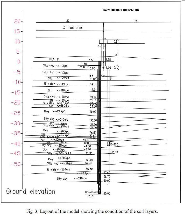
Another analysis is to check the model shown in Fig. 3 and calculating many parameters by using the Plaxis program for three dimensional analyses for finite elements. The analysis of the program depends on the same of soil investigations information and parameters of the soil strength. In the finite element analysis, the Mohr-Coulomb model with undrained conditions is used to simulate the constitutive relationship for the soil material and the linear elastic non-porous material model was used for the piles and pile cap of reinforced concrete structure.
7.1 Construct Modes for the Model
1- The gravity is applied to the original configuration, simulating the initial stress field.
2- Construction is started from drilling holes until completion of the superstructure. During construction, consolidation occurs in soils and settlement of the pile group is calculated. , reset displacement to zero.
3- Construct of the pile cap.
4- A greater load is applied to find the ultimate bearing capacity of the pile group, reset displacement
to zero.
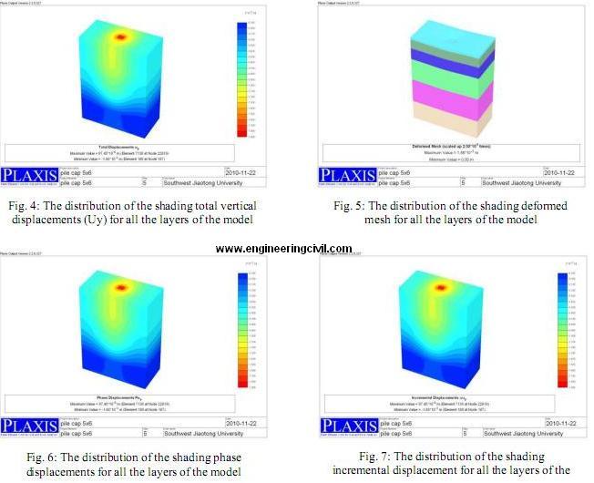
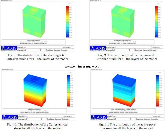
The load applied in the model is the same of that using for the previous design and analysis. The results of the numerical analysis are shown in Figures from 4 to 11. The displacement value can be shown in Fig. 4, 5, 6 and 7 that the maximum value for displacement equal to -1.88 mm, the minus sign refers to the direction of the displacement to down, when compared this value with maximum value maintained from manual calculation shown in Figs. 1 and 2 is relatively little value that in the considerations for the numerical analysis more be accepted. Another values are maintained from the numerical calculations like incremental displacement, total Cartesian strain, incremental Cartesian strain, Cartesian total stress and pore water pressure, all these calculations are reasonable. Fig. 11 shows the indication for active stress of the soil; therefore, these values of the pore pressure are relatively small and during the time of the consolidation of the structure will not increase the final value of the consolidation settlement.
8. Conclusion
– The design of a Bridge or any other structure with more than one code gives a difference in the design due to the nature of the country that using this code.
– In this paper it can be seen the more safety with design in the Chinese code than the AASHTO code that the second code do not take the effect of the earthquake in the design.
– The settlement calculated for this study satisfies the requirement of normal operation of a high speed rail.
– The bearing capacity of the pile group is sufficient.
– The bridge also satisfies the requirement of normal operation of a high-speed rail.
– The analysis with 3D Plaxis program gives accepted results with that of calculated analysis by using equation 6, which provide more check for the design of the bridge and gives more agreement and suitability for the design.
References:
1. AASHTO (1998), “AASHTO-LRFD Bridge Design Specifications”, Customary US Units, second edition, Washington, DC.
2. Braja M. Das, “Principles of Foundation Engineering”, Sixth Edition.
3. “British Standard 5400”, University of Sheffield, 16 December 2002, Uncontrolled Copy, (c) BSI
4. “The Chinese National Standard (CNS, 2002)”. Building foundation design code (GB50007-2002), China Building Industry Press, Beijing (in Chinese).
5. Wan Ikram Wajdee b; Wan Ahmad Kamal, “Comparison of bridge design in Malaysia between American codes and British codes”, University Technology Malaysia MAC , 2005.
6. Skempton, A. W.; McDonald, D. M. (1956). “The allowable Settlement of Buildings”, Proceeding of Institute of Civil Engineers, Vol. 5, Part III, p. 727.
We at engineeringcivil.com are thankful to Sir Hussein for submitting this research paper to us. We hope this will be of great use to many civil engineering students around the world.
If you have a query, you can ask a question here.
thankq sir for this analysis……would u like to give an analysis of this problem ……
analysis and design of a steel bridge having rail load (i.e. railway bridge)
by mistake 4 pile group shifted along the C/L, and observe Shaft is on 2 piles How I calculate its Live loads of this pile