By
Prof. V.D.Gundakalle, Professor ,Department of Civil Engineering, K.L.E. College of Engineering and Technology, Belgaum, Karnataka, (India)
Prof.Abhishek.S.Pathade, Professor, Department of Civil Engineering, K.L.E. College of Engineering and Technology, Belgaum, Karnataka, (India).
Mubashar Munshi Post Graduation Student, K.L.E. College of Engineering and Technology, Belgaum, Karnataka, (India).
Abstract
The actual earthquake force in considerably higher than what the structures are designed for. We cannot design the structures for the actual value earthquake intensity because the cost of construction will be too high. The actual intensity of earthquake is reduced by a factor called response reduction factor ‘R’. The value of ‘R’ depends on how we design the frame members. From previous study it is noted that the ‘R’ factor depends on ductility factor (Rµ), strength factor (Rs), structural redundancy (RR) and damping associated with structure. The objective of this work is to evaluate the response modification factor (R) for RC elevated water tanks supported on framing system are considered having staging height of 15m and 21m with varying capacities and staging configuration. These tanks are designed for gravity as well as seismic loads. A non-linear pushover analysis is used to calculate the base shear capacity and ductility of tanks. Two different cases of collapse criterion are used for defining ultimate stage on the capacity curve. It is observed that the Rµ are increasing with time period but the variation is not consistent. RS is higher for lower staging height.
Key words
Response reduction factor, Seismic design, static nonlinear pushover analysis
1. INTRODUCTION
The concept of R factor is based on the observations that well detailed seismic framing systems can sustain large inelastic deformations without collapse and have excess of lateral strength over design strength. It is found that R factor is depends on ductility factor (Rµ), structural over strength, structural redundancy and damping associated with structure. Each of above factor further depends on parameters discussed below. Ductility factor is defined as the ratio of elastic strength demand imposed on structure to inelastic strength
demand for a given ductility ratio (µ).
The Rµ factor is function of displacement ductility, fundamental time period, and ground motion characteristics, type of foundation strata and characteristics parameters of hysteretic models. Structural over strength (Rs) is defined as ratio of maximum lateral yield strength of structure to code specified design base shear. It accounts the excess strength because of load factors in various design load combinations, reduced design strengths of materials by factor of safety.
ATC-40 has developed modeling procedure, acceptance criteria and analysis procedures for pushover analysis. This document defines force-deformation criteria for hinges used in pushover analysis.
As shown in Figure.1 , five points labeled A, B, C, D, and E are used to define the force deflection behavior of the hinge and three points labeled IO, LS and CP are used to define the acceptance criteria for the hinge. (IO, LS and CP stand for Immediate Occupancy, Life Safety and Collapse Prevention respectively). The values assigned to each of these points vary depending on the type of member as well as many other parameters defined in the ATC-40[3]
SAP 2000 software is used to perform the static pushover analysis. The user establishes grid lines, places structural objects relative to the grid lines using points, lines and areas, and assigns loads and structural properties to those structural objects (for example, a line object can be as-signed section properties; an area object can be assigned slab properties). The program simplifies seismic analysis by providing modeling features such as rigid diaphragms to model slabs. Analysis and design are then performed based on the structural objects and. It can take the results of an analysis as input to define the hinge properties of members so that pushover analysis can be carried out. Results are generated in graphical or tabular form that can be printed to a printer or to a file for use in other programs.
In the present study the gravity load analysis and lateral load analysis as per the seismic code IS 1893 (Part 1): 2002 are carried out on water tank and an effort is made to study the effect of seismic loads on them and their capacity and demand is evaluated using nonlinear static pushover analysis guidelines given in ATC-40.
2. Structural modeling
The RC beams and columns are modeled as three dimensional frame elements with centerline dimension. Slabs are modeled as membrane elements and are assumed to behave as rigid diaphragms. Column foundations are assumed to be fixed. Damping ratio of 5 percent is assumed for all natural modes. For the nonlinear static analysis, rigid zone factor of unity is assigned to beam-column joints. Flexure moment (M3), axial biaxial moment (PM2M3) and axial compressive force (P) hinges are assigned at the face of beam, column, and Bracing respectively. The ATC [40] document for concrete building lays down modeling procedures for pushover analysis. This document defines force-deformation criteria for hinges used in pushover analysis.
2.1 Water tank description
In the present study elevated water tanks rectangle in plan are considered for different staging height. For 150 m3, and 200 m3capacity ESR has a staging configuration of 9 columns, 3x 3 grid in X-direction and Y-direction Figure 2. For 600 m3capacity ESR has a staging configuration of 16 columns, 4 x 4 grid in X-direction and Y-direction Figure 3. For uniformity and simplicity, all beam sizes and column sizes are kept uniform. All structural members are designed and ductile detailing as per IS 13920 .For deriving relations with ductility, ‘R’ factor against time period, zones.Following models are considered.
15m and 21m staging height with 150 m3, 200 m3and 600 m3 capacity of tank for seismic zones II, III, IV, V.
Design data for the buildings considered are as follows:
Grade of concrete M20, steel Fe415, density of concrete= 25kN/m3, Elastic modules of concrete (Ec)= 22.36×10⁵ kN/m2, live load intensities for roof slab =1.25kN/m2. In the seismic weight calculation, only 25% of the floor live load is considered. R as per international standards for elevated tanks:
IBC 2000 / FEMA 368 – R = 1.5 to 3.0
AWWA D110 – Rc = 1, Ri = 2 to 2.75
ACI 350.3 – R = 2.0 to 4.75
IS:1893 – 2002 (part – 2)
RCC frame support – R = 2.5
3. Analysis procedure
Developing a three dimensional model of RCC frame
I Application of gravity loads, live loads, water load, etc.
II Application of static lateral load induced due to earthquake, at CG of container.
III Pushing the structure using the load patterns of static lateral loads, to displacements larger than those
associated with target displacement using static pushover analysis.
IV Developing pushover curve and estimating the force and deformations in each element at the level of displacement corresponding to target displacement.
The tank was designed and detailed in accordance with the codal provisions of IS:1893 – 1984 and IS: 13920 – 1993. The container and framing system is modeled in SAP2000 for performing static pushover analysis.
Assign hinge properties available in SAP2000 as per ATC-40 to the frame elements. For a beam default hinges that yield based upon flexure (M3) is assigned. For the column default hinges that yield based upon the interaction of the axial force and bending moment (P-M2-M3) is assigned. For a bracing default hinges that yield based upon flexure (M3) is assigned. After assigning hinge properties to the structure, the static pushover cases were defined. Typically, the gravity loads were applied first and then subsequent lateral static pushover load cases were specified to start from the final conditions of the gravity pushover in the gravity case, the structure was loaded with the dead load and 25% of the live load. The application of gravity loads was force-controlled whereas the application of lateral loads was displacement-controlled. The first mode response of the structure was assigned as the load pattern for the lateral push applied to the structure. The procedure involves applying horizontal loads, in a prescribed pattern, to a computer model of the structure, incrementally; i.e., “pushing” the structure; and plotting the total applied shear force and associated lateral displacement at each increment [1]. From the analysis, the base shear (V) versus roof displacement (Delta (D)roof) curve of the structure, usually called static pushover curve, is obtained Pushing the structure using the load patterns of static lateral loads, to displacements larger than those associated with target displacement using static pushover analysis. The maximum limit for the roof displacement is specified as 0.004H, where H is the height of the structure [2]. The base shear and roof displacement is recorded at every step. The final output is the static pushover curve.
Due to plan symmetry of structure, the pushover analysis is carried out in X direction only. Hence, earthquake loads of tank full condition is given in X-direction only.
4. Results and discussions
4.1 Performance point and location of hinges
From result it’s observed that the First hinged formed at 5th Step. The maximum number of hinges formed in elastic range only. Hence, it indicates that there is a need of retrofitting for members.
Estimation of strength factor:
Maximum Base Shear Vo= 1243.78 k N
(from pushover curve)
Design Base shear Vd = 304.72 k N (as per EQ calculation)
Using equation for strength factor, given in ATC – 19
Rs = Vo/ Vd = 1243.78 / 304.72 = 4.08
Rs = 4.08
[2]. Estimation of ductility factor:
Maximum drift capacity Delta m = 85mm
(0.004 H)
Yield drift Delta y = 56mm (from pushover curve)
Using equation for displacement ductility ratio, given in ATC – 19
3. Estimation of redundancy factor:
Table 2. From ATC – 19 Lines of vertical seismic framing
|
Lines of vertical seismic framing |
Drift redundancy factor |
|
2 |
0.71 |
|
3 |
0.86 |
|
4 |
1 |
RR = 1
4. Estimation of response reduction factor R:
R = Ro. Ru. RR
R = 4.08 x 1.78 x 1
R = 7.26
Hence the value of response reduction factor.
4.1 Result for different cases
Table 3 Result of 150 m3 Capacity ESR for 15m staging height
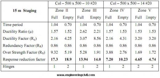
Table 4 Result of 150 m3 Capacity ESR for 21m staging height
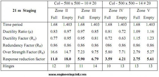
Table 5 Result of 200 m3 Capacity ESR for 15m staging height
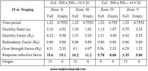
Table 6 Result of 200 m3 Capacity ESR for 21m staging height
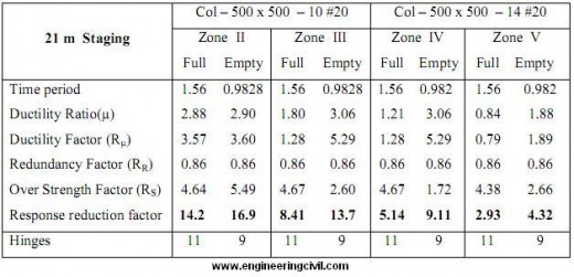
Table 7 Result of 600 m3 Capacity ESR for 15m staging height
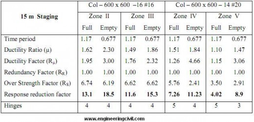
Table 8 Result of 600 m3 Capacity ESR for 21m staging height

5. CONCLUSION
Based on analytical investigations and tank details assumed, following conclusion is arrived:
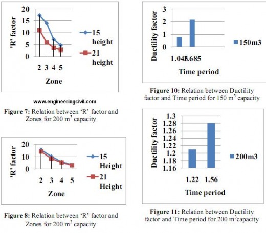
1. The ‘R’ factor reduces as zone increases.
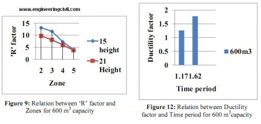
2. It is observed that R factor increases with time period but the variation is not consistent. It varies from 2.75 to 4.65, for tank full condition in zone V.
3. The contribution of Rµ factor in ‘R’ factor increases with increase in time period.
4. To ensure the consistent level of damage, values of R should depend on both fundamental period of the staging and the soil type.
5. The values assigned to R for a given framing system should vary between seismic zones. Also detailing
requirements vary by zone.
6. Estimation of R factor with exact analysis will help in an economical design.
7. It is observed that R factor varies from 4.32 to 8.90, for tank empty condition in Zone V.
Notations
DL – Dead Load
LL – Live Load
EL – Earthquake load
VB – Design seismic base shear
Ru – Ductility factor
u – Displacement ductility ratio
RR – Redundancy factor
RS – Strength factor
Vo – Maximum design base shear force
m – Maximum drift capacity
Delta y – Yield drift
Vd – Design base shear force
IO – Immediate Occupancy
LS – Life Safety
CP – Collapse Prevention
References
[1] ATC-19, ‘Structural response modification Factors’, 1995.
[2] ATC 40 (1996): “Seismic Evaluation and Retrofit of Concrete Buildings”, Volume1, ATC-40 Report, Applied Technology Council, Redwood City, California.
[3] Andrew Whittker, Gary hart and Christopher Rojahn, “Seismic Response Modification Factors”, journal of structural engineering, Vol.125, April 1999. period buildings’, Earthquake Spectra, Vol. 5, No. 3, pp.571-590, (1989).
[4] Dr. Jain S.K, Dr. Durgesh Rai, ‘Guide lines for Seismic design of liquid storage tanks’.
[5] Fajfar P, ‘A nonlinear analysis method for performance based seismic design’, Earthquake Spectra, Vol. 16, No. 3, pp.573-592, (2000).
[6] FEMA 273, ‘NEHRP Guidelines for the Seismic Rehabilitation of Buildings’ 1999.
[7] Habibullah, A. and Pyle, S. (1998): “Practical Three Dimensional Nonlinear Static Pushover Analysis”, Published in Structure Magazine, Winter, 1998.
[8] Ioana Olteanu and M. Budescu, “The Ductile Design Concept for Seismic Actions in Miscellaneous Design Codes”, “Gheorghe Asachi” Technical University of Ia?i, November 15, 2009
9] IS 1893 (Part I) 2002, ‘Criteria for Earthquake Resistant Design of Structures’.
[10] Mander JB, Priestley MJN, Park R, ‘Theoretical stress–strain model for confined concrete’, Journal Structural Engineering, ASCE, Vol. 114, No.8, pp.1804–1826, (1988).
[11] Mr. Bhavin Patel and Mrs. Dhara Shah, ‘Formulation of Response Reduction Factor for RCC Framed
Staging of Elevated Water Tank, World Congress on Engineering 2010, London, U.K.
[12] Riddle R. Hidalgo P. and Cruz E., ‘Response Modification Factors for earthquake resistant design’ 1988).
We at engineeringcivil.com are thankful to Er. Mubashar for submitting this research paper and helping all civil engineers understand how to Evaluate Response Reduction Factor for RC Elevated Water Tanks
If you have a query, you can ask a question here.


What R value is used in the linear static design and analysis ? Does this selected value affects the final result?
Dear Mubashar,
Very good paper explaining easily without many technical jargon.