

By
Sourav Dutta
Manager-Civil
Ion Exchange India Limited
Conventional way of rebar lapping / splicing as per BIS
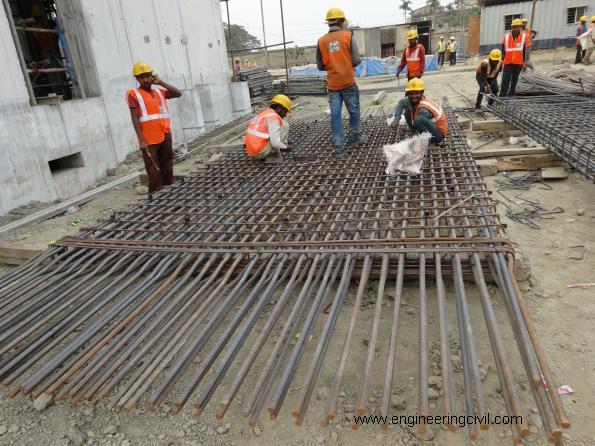
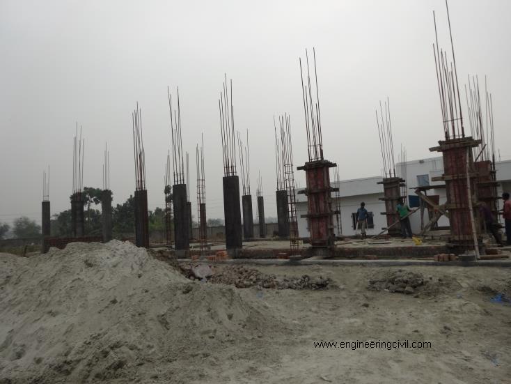
Photo 1 : Typical rebar exposure/extension for further lapping/splicing
As per BIS456-2000 some guidelines on lapping/splicing are as follows:
- Lap splices shall not be used for bars larger than 32 mm. Bars huger than 32 mm shall be welded (based on guidelines of IS9417) or mechanically spliced.
- Congestion of reinforcement should be avoided during detailing.
The guideline of lap length / development length of rebar required for lapping / splicing is as follows:
| Grade of RCC | M20 | M25 | M30 | M35 |
| Grade of Rebar | Lap length required in tension as per Cl. 26.2.1 of BIS456-2000: | |||
| Fe500 | 57 x d | 50 x d | 45 x d | 40 x d |
| Fe600 | 68 x d | 60 x d | 55 x d | 48 x d |
Note: d = nominal diameter of HYSD bar
Some disadvantages of this conventional method of rebar lapping / splicing:
The above table along with photo 1 clearly indicates how much lap length we need to provide for lapping, conversely how much rebar and binding wires we might save if we might use mechanical splicing for joining the rebar.
More lapping of rebar causes congestion, and if vibrator doesn’t percolate through the congestion and compact the surrounding concrete around the splice/lap location, it is likely to create honeycomb or voids in concrete, as shown in photo 2. That is one of the main reasons that although 6% rebar is permissible in columns as per Cl. 26.5.3.1 of BIS456-2000, not more than 4% rebar is advised as per NOTE of the clause.

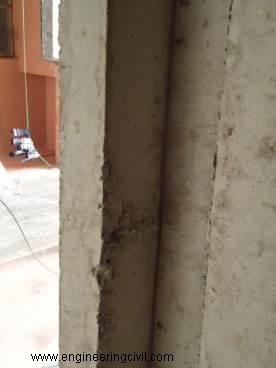
Photo 2
As per Cl. 26.5.3.3 of BIS456-2000, at splice location longitudinal bars in a column are required to be inclined with the axis of column at a slope not exceeding 1 in 6, as shown in photo 3. Such profile is difficult to fabricate accurately without automated bending machine, which incur huge hire charges. Moreover such fabrication involves a lot of labour dependency and time engagement.
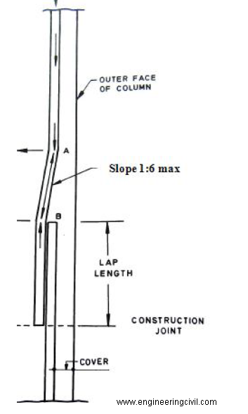
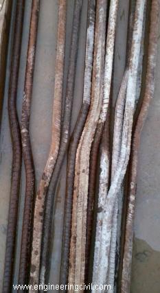
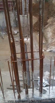
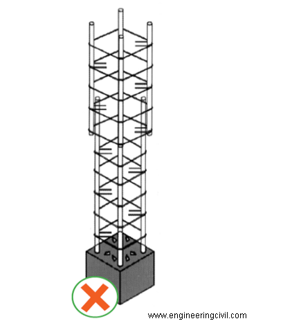
Photo 3
Now-a-days mechanical splicing system technology is developed where rebar couplers are designed to join reinforcement bars of dia ranging from 12mm to 40mm dia. The traditional method of connecting reinforcement bars with lap joints continuity in reinforced concrete need not be always appropriate. Advantages of simplicity and economy in lap splicing are limited to smaller diameter bars. Mechanical couplers offer the solution for splicing when large diameter bars are involved.
The processes and machines involved in rebar coupling process are as follows in photo 4:
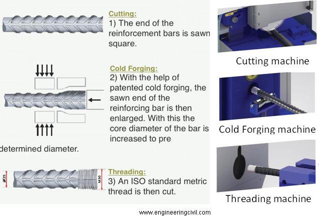
Photo 4
The advantages of mechanical splicing system (shown in photo 5) over conventional rebar lapping system are as follows:
- Rebar couplers are manufactured with tensile strength superior than tensile strength of rebar, for proper compatibility.
- Rebar coupler performs like continuous reinforcement. Thus no staggering of reinforcement bars required for splicing as per BIS456-2000 Cl.26.2.5. Moreover, the continuity of rebar offers excellent provision for grounding electrical current.
- Rebar Couplers reduce rebar congestion and improve concrete flow and compaction (which is likely to reduce honeycombing or voids as shown in photo 2). Workability with higher steel-to-concrete ratio allows optimum sizing of RCC structural members.
- Since no rebar staggering is necessary, multiple reuses of formworks are possible.
- Rebar coupler increase productivity of work at site because of reduced installation time and simper quality control requirements.
- Rebar coupler leads to savings of cost of rebar to be lapped, binding wires, wastage of rebar, skilled labour charges savings in bending component involved in fabrication of rebar. Also automated bending machine involvement not necessary and rebar threading cycle time is faster in comparison. Thus a lot of time savings possible and it is economical to use.
| Table for Cost Comparison between Rebar Coupler and conventional Lapping Process for a single lap | |||||||||||
| Bar Dia. d (mm) | Average Lap length for comparison = 50xd (m) | Weight of lapping (Kg) | Rebar Cost/Kg (Rs) | Rebar Cost (Rs) | Binding wire for lapping @ 5Kg/T (Kg) | Binding wire cost including tax (Rs) | Binding wire Cost (Rs) | Labour cost for bending @ Rs2/Kg | Total Lapping Cost (Rs) | Coupler Rate + rebar threading (Rs) | SAVINGS (Rs) |
| 40 | 2 | 19.7 | 35 | 690.5 | 0.10 | 75 | 3.5 | 39.5 | 733.4 | 270 | 463 |
| 36 | 1.8 | 14.4 | 503.4 | 0.07 | 2.5 | 28.8 | 534.7 | 206 | 329 | ||
| 32 | 1.6 | 10.1 | 353.5 | 0.05 | 1.8 | 20.2 | 375.5 | 154 | 222 | ||
| 25 | 1.25 | 4.8 | 168.6 | 0.02 | 0.8 | 9.6 | 179.1 | 110 | 69 | ||
| 20 | 1 | 2.5 | 86.3 | 0.01 | 0.4 | 4.9 | 91.7 | 85 | 7 | ||
| 16 | 0.8 | 1.3 | 44.2 | 0.01 | 0.2 | 2.5 | 46.9 | 60 | -13 | ||
- Rebar couplers are better for connecting precast RCC members with full tension splice.
- Rebar couplers are more reliable than lap splicing as mechanical splices doesn’t depend on concrete for load transfer.
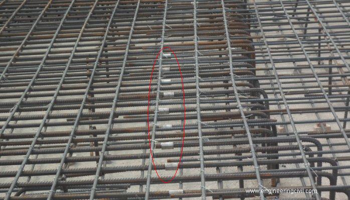
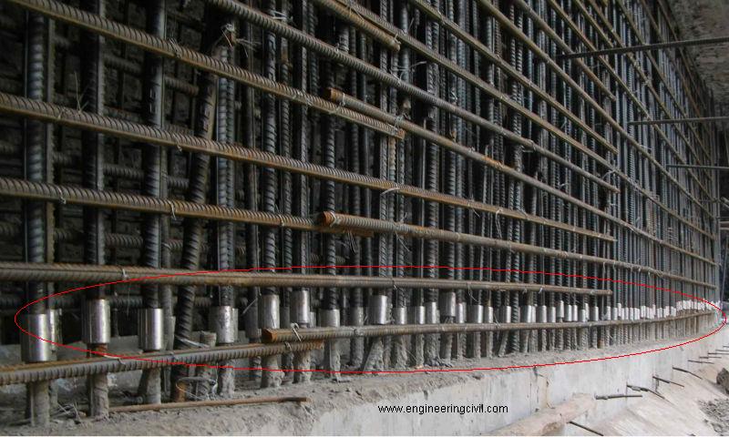
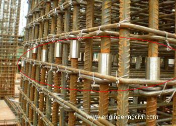
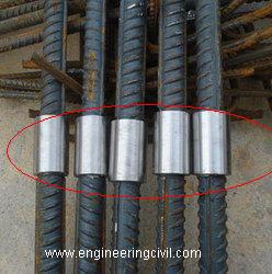
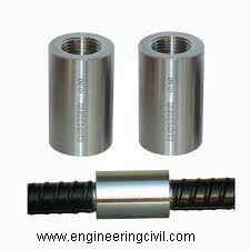
Photo 5 : Mechanical splicing (rebar couplers) used in various projects
We at engineeringcivil.com are thankful to Er. Sourav Dutta for submitting this paper to us. We hope this paper will be helpful for the whole construction industry in general.
If you have a query, you can ask a question here.