Keywords: planimeter, Computation of area, zero circle
Instrumental methods are one of the important technique uses to determine area of a plot. The other methods for area computation are using field notes and from previously plotted plan. We have already discussed them here.
Computation of areas and volumes | Computation of Area from Plan
Significance of Planimeter in Area computation
The planimeter gives more accurate (within one percent) results compared to the other methods except by direct calculation from the field notes. It is used for determining the areas of figures plotted to scale, especially when the boundaries are irregular. Example for such plots are, plot with irregular boundary and plot having a river as boundary on one side.

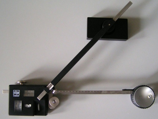
Figure 1: Planimeter (Source: britannica.com)
What is planimeter?
The working principle of the Amsler Polar planimeter, which is in common use, is described below. The planimeter consists of two arms hinged at a point calls the pivot points. One of the arms is called the anchor arms and is of fixed length. At the end of the anchor arm is a needle –point (called the anchor point), which is used to fix the anchor on the paper. The anchor arm has a small weight at the end, figure 1.
The other arm(called the tracing arm) carries a tracing point, which is moved round the boundary of the area to be measures. A wheel whose axis is parallel to the tracing arm measures the area of the plot.
The wheel carries a graduate drum divided into 100 parts, the tenths of a part being read on the vernier. Then only the complete revolutions of the wheel or roller are read on the counting disc or dial to which the wheel is attached. The counting disc is divided into ten equal parts and advances one line at every full turn of the wheel. The counting disc performs one revolution at every 10 turns of the wheel.
Each reading is a figure of 4 digits, the unit part being read on the counting disc, he tenths and the hundredths in the drum, and the thousandths on the vernier. When the zero of the wheel is opposite the zero of the vernier, the mark of the counting disc should be opposite the index mark. However, this may not always be true due to the imperfections of the gear.
The planimeter is connected on three points such as the anchor point, the tracing point and in the periphery of the wheel. When the tracing point is moved around the outline of the plot figure, the graduated wheel partly rotates and partly slips. This is because the normal component of the motion causes rotation, while the axial component of the motion causes slip. But this slip does not affect the reading. The total amount of rotation of the wheel measures is the total normal displacement. Thus the complete area is covered in this process.
Actual methods and procedure for the measurement of area is discussed in the next article. Check it out here.
If you have a query, you can ask a question here.


