

Introduction to Pre Engineered Buildings
Technological improvement over the year has contributed immensely to the enhancement of quality of life through various new products and services. One such revolution was the pre engineered buildings. Through its origin can be traced back to 1960’s its potential has been felt only during the recent years. This was mainly due to the development in technology, which helped in computerizing the design and design.
Though initially only off the shelf products were available in these configurations aided by the technological development tailor made solutions are also made using this technology in very short durations. A recent survey by the Metal Building Associations (MBMA) shows that about 60% of the non residential low rises building in USA are pre engineered buildings.
Although PEB systems are extensively used in industrial and many other non residential constructions world wide, it is relatively a new concept in India. These concepts were introduced to the Indian markets lately in the late 1990’s with the opening up of the economy and a number of multi nationals setting up their projects.The market potential of PEB’s is 1.2 million tones per annum. The current pre engineered steel building manufacturing capacity is 0.35 million tones per annum. The industry is growing at the compound rate of 25 to 30 %.
With respect to design of the structure and aesthetic appearance India is way behind. Indian manufacturers are trying to catch up; comparatively PEB’s is a new concept in India. Beside, in fabrication and other areas of PEB India is very good. As compared to other countries Indian codes for building design are stringent but safer. IS standards are upgraded continuously. In India, American codes are also followed.
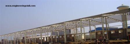
Pre engineered steel buildings can be fitted with different structural accessories including mezzanine floors, canopies, fascias, interior partitions etc. and the building is made water proof by use of special mastic beads, filler strips and trims. This is very versatile buildings systems and can be finished internally to serve any functions and accessorized externally to achieve attractive and unique designing styles. It is very advantageous over the conventional buildings and is really helpful in the low rise building design.
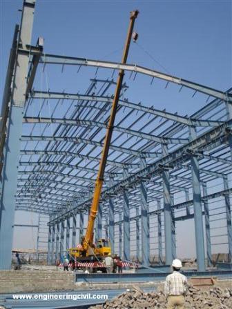
Pre engineered buildings are generally low rise buildings however the maximum eave height can go upto 25 to 30 metres. Low rise buildings are ideal for offices, houses, showrooms, shop fronts etc. The application of pre engineered buildings concept to low rise buildings is very economical and speedy. Buildings can be constructed in less than half the normal time especially when complemented with the other engineered sub systems.
The most common and economical type of low rise buildings is a building with ground floor and two intermediate floor plus roof. The roof of low rise buildings may be flat or sloped. Intermediate floors of low rise buildings are made of mezzanine systems. Single storied houses for living take minimum time for construction and can be built in any type of geographical location like extreme cold hilly areas, high rain prone areas, plain land obviously and extreme hot climatic zones as well.
Applications of Pre Engineered Buildings (PEB)
1. WAREHOUSES
2. FACTORIES
3. WORKSHOPS
4. OFFICES
5. GAS STATIONS
6. VEHICLE PARKING SHEDS
7. SHOWROOMS
8. AIRCRAFT HANGARS
9. METRO STATIONS
10. SCHOOLS
11. RECREATIONAL
12. INDOOR STADIUM ROOFS
13. OUTDOOR STADIUM CANOPIES
14. BRIDGES
15. RAILWAY PLATFORM SHELTERS
Advantages of Pre Engineered Buildings
REDUCED CONSTRUCTION TIME: Buildings are typically delivered in just a few weeks after approval of drawings. Foundation and anchor bolts are cast parallel with finished, ready for the site bolting. Our study shows that in India the use of PEB will reduce total construction time of the project by at least 50%. This also allows faster occupancy and earlier realization of revenue.
LOWER COST: Due to the systems approach, there is a significant saving in design, manufacturing and on site erection cost. The secondary members and cladding nest together reducing transportation cost.
FLEXIBILTY OF EXPANSION: Buildings can be easily expanded in length by adding additional bays. Also expansion in width and height is possible by pre designing for future expansion.
LARGE CLEAR SPANS: Buildings can be supplied to around 80M clear spans.
QUALITY CONTROL: As buildings are manufactured completely in the factory under controlled conditions the quality is assured.
LOW MAINTENANCE : Buildings are supplied with high quality paint systems for cladding and steel to suit ambient conditions at the site, which results in long durability and low maintenance coats.
ENERGY EFFICIENT ROOFING AND WALL SYSTEMS: Buildings can be supplied with polyurethane insulated panels or fiberglass blankets insulation to achieve required “U” values.
ARCHITECTURAL VERSTALITY: Building can be supplied with various types of fascias, canopies, and curved eaves and are designed to receive pre cast concrete wall panels, curtain walls, block walls and other wall systems.
SINGLE SOURCE RESPONSIBILTY: As the complete building package is supplied by a single vendor, compatibility of all the building components and accessories is assured. This is one of the major benefits of the pre engineered building systems.
Pre Engineered Buildings Vs Conventional Steel Buildings
| PROPERTY | PEB BUILDINGS | CONVENTIONAL STEEL BUILDINGS |
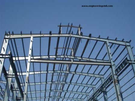
| STRUCTURE WEIGHT | Pre engineered buildings are on the average 30% lighter because of the efficient use of steel. Primary framing members are tapered built up section. With the large depths in areas of higher stress. | Primary steel members are selected hot rolled “T” sections. Which are, in many segments of the members heavier than what is actually required by design? Members have constant cross section regardless of the varying magnitude of the local stresses along the member length. |
| Secondary members are light weight roll formed “Z” or “C” shaped members. | Secondary members are selected from standard hot rolled sections which are much heavier. |
| DESIGN | Quick and efficient: since PEB’s are mainly formed by standard sections and connections design, time is significantly reduced. Basic design based on international design codes are used over and over. | Each conventional steel structure is designed form scratch with fewer design aids available to the engineer. |
| Specialized computer analysis design programs optimize material required. Drafting is also computerized using standard detail that minimize the use of project custom details. | Substantial engineering and detailing work is required from the very basic is required by the consultant with fewer design aids. | |
| Design shop detail sketches and erection drawings are supplied free of cost by the manufacturer. Approval drawing is usually prepared within in 2 weeks. | Extensive amount of consultant time is devoted to the alterations that have to be done. | |
| PEB designers design and detail PEB buildings almost every day of the year resulting in improving the quality of designs every time they work | As each project is a new project engineers need more time to develop the designs and details of the unique structure. | |
| DELIEVERY | Average 6 to 8 weeks | Average 20 to 26 weeks |
| FOUNDATIONS | Simple design, easy to construct and light weight. | Extensive, heavy foundation required. |
| ERECTION SIMPLICITY | Since the connection of compounds is standard the learning curve of erection for each subsequent project is faster. | The connections are normally complicated and differ from project to project resulting tin increasing the time for erection of the buildings. |
| Periodic free of charge erection is provided at the site by the manufacturer. | There has to be separate allocation of labour for the purpose of erection. | |
| ERECTION COST AND TIME | Both costs and time of erection are accurately known based upon extensive experience with similar buildings. | Typically, conventional steel buildings are 20% more expensive than PEB in most of the cases, the erection costs and time are not estimated accurately. |
| The erection process is faster and much easier with very less requirement for equipment. | Erection process is slow and extensive field labour is required. Heavy equipment is also needed. | |
| SEISMIC RESISTANCE | The low weight flexible frames offer higher resistance to seismic forces. | Rigid heavy frames do not perform well in seismic zones. |
| OVER ALL PRICE | Price per square meter may be as low as by 30 % than the conventional building. | Higher price per square meter. |
| ARCHITECTURE | Outstanding architectural design can be achieved at low cost using standard architectural details and interfaces. | Special architectural design and features must be developed for each project which often require research and thus resulting in higher cost. |
| SOURCING AND COORDINATION | Building is supplied complete with all accessories including erection for a single “ONE STOP SOURCE”. | Many sources of supply are there so it becomes difficult to co ordinate and handle the things. |
| COST OF CHARGE ORDER | PEB manufactures usually stock a large amount of that can be flexibly used in many types of PEB projects. | Substitution of hot rolled sections infrequently rolled by mills is expensive and time consuming. |
| Change orders are easily accommodated at all stages of the order fulfillment process. Little or no material is wasted even if a change order is made after fabrication starts. | Change orders that are made after the dispatch of hot rolled sections result in increasing the time and cost involved in the project. | |
| BUILDING ACCESSORIES | Designed to fit the system with standardized and inter changeable parts. Including pre designed flashing and trims. Building accessories are mass produced for economy and are available with the building. | Every project requires different and special design fro accessories and special sourcing for each item. Flashing and trims must be uniquely designed and fabricated. |
| FUTURE EXPANSIONS | All project records are safely and orderly kept in electronic format which make sit easy for the owner to obtain a copy of his building record at any time. | It would be difficult to obtain project records after a long period of time. It is required to contact more than one number of parties. |
| Future expansion is very easy and simple. | Future expansion is most tedious and more costly. | |
| SAFETY AND RESPONSIBILTY | Single source of responsibility is there because all the job is being done by one supplier. | Multiple responsibilities can result in question of who is responsible when the components do not fit in properly, insufficient material is supplied or parts fail to perform particularly at the supplier/contractor interface. |
| PERFORMANCE | All components have been specified and designed specially to act together as a system for maximum efficiency, precise fir and peak performance in the field. | Components are custom designed for a specific application on a specific job. Design and detailing errors are possible when assembling the diverse components into unique buildings. |
| Experience with similar buildings, in actual field conditions world wide, has resulted in design improvements over time, which allow dependable prediction of performance. | Each building design is unique, so predication, of how components will perform together is uncertain. Materials which have performed well in some climates may not do well in other conditions. |
Design of Pre Engineered Buildings (PEB)
The main framing of PEB systems is analyzed by the stiffness matrix method. The design is based on allowable stress design (ASD) as per the American institute of Steel Construction specification or the IS 800. the design program provides an economic and efficient design of the main frames and allows the user to utilize the program in different modes to produce the frame design geometry and loading and the desired load combinations as specified by the building code opted by the user. The program operates through the maximum number of cycles specified to arrive at an acceptable design. The program uses the stiffness matrix method to arrive at an acceptable design. The program uses the stiffness matrix method to arrive at the solution of displacements and forces. The strain energy method is adopted to calculate the fixed end moments, stiffness and carry over factors. Numerical integration is used.
Design Cycle
The design cycle consists of the following steps:
1. Set up section sizes and brace locations based on the geometry and loading specified for the frame design.
2. Calculate moment, shear, and axial force at each analysis point for each load combination.
3. Compute allowable shear, allowable axial and allowable bending stress in compression and tension at each analysis point.
4. Compute the corresponding stress ratios for shear, axial and bending based on the actual and allowable stresses and calculate the combined stress ratios.
5. Design the optimum splice location and check to see whether the predicted sizes confirm to manufacturing constraints.
6. Using the web optimization mode, arrive at the optimum web depths for the next cycle and update the member data file.
7. At the end of all design cycles, an analysis is run to achieve flange brace optimization.
Frame Geometry
The program has the capability to handle different types of frame geometry as follows
Frames of different types viz. rigid frames, frames with multiple internal columns, single slope frames, lean to frames etc.
Frames with varying spans, varying heights and varying slopes etc.
Frames with different types of supports viz. pinned supports, fixed supports, sinking supports, supports with some degrees of freedom released.
Unsymmetrical frames with off centric, unequal modules, varying slopes etc.
User specified purlin and girt spacing and flange brace location.
Frame Loading
Frame design can handle different types of loadings as described below:
All the building dead loads due to sheeting, purlins, etc. and the self weight of the frame.
Imposed live load on the frame with tributary reductions as well.
Collateral load such as false ceiling, light fixtures, AC ducting loads, sprinkler systems and many other suspended loads of similar nature.
Wind loads input such as basic wind speed or basic wind pressure that will be converted to deign wind pressure as per the building code specified by the user and shall be applied to the different members of the building according to the coefficients mentioned in the codes prescribed by the user. The standard building codes like MBMA, UBC, ANSI, IS:875 part 3 etc are used fro this purpose.
Crane and non crane loading can be specified by the user and the program has the capability to handle these special loads and combine them with the other loads as required.
Seismic loads corresponding to the different zone categories of various international codes can also be defined and combined with other load cases as required.Temperature loads can also be specified in the form of different differential temperature value on centigrade and specifying the appropriate coefficient for the thermal expansion.Load combinations with appropriate load factors can be specified by the user as desired.
Design Codes
Following are the main design codes generally used:
AISC : American institute of steel construction manual
AISI : American iron and steel institute specifications
MBMA : Metal building manufacturer’s code
ANSI : American national standards institute specifications
ASCE : American society of civil engineers
UBC : Uniform building code
IS : Indian standards
Design Criteria
DESIGN METHOD: Allowable stress design method is used as per the AISC specifications.
DEFLECTIONS: Unless otherwise specified, the deflections will go to MBMA, AISC criteria and standard industry practices.
PRIMARY FRAMING: Moment resisting frames with pinned or fixed bases.
SECONDARY FRAMING: Cold formed Z sections or C sections for purlins or girts designed as continuous beams spanning over rafters and columns with laps.
LONGITUDANAL STABILITY: Wind load on building end walls is transferred through roof purlins to braced bays and carried to the foundations through diagonal bracing.
DESIGN SOFTWARE: The latest software that is used for design is STAAD 2007.
DESIGN PROCESS
The frame data is assembled based on number of frame members, number of joints, number of degrees of freedom, the conditions of restraint and the elastic properties of the members. Based on this, the data is stored and member section properties are computed. The overall joint stiffness matrix is obtained based on the above frame data by summation of individual stiffness matrices considering all possible displacements. The load vector is then generated based on the loading data and the unknown displacements are obtained by inverting the overall joint stiffness matrix and multiplying with the load vector.
Knowing the free joint displacements
REPORT ON PLANT VISIT
DEPARTMENTS IN THE PLANT
PRODUCTION, PLANNING & CONTROL (PPC)
SHEARING
BUILT UP
FINISHING
COLD FORM
SHIPPING
QUALITY CONTROL
MAINTENANCE (ELECTRICAL)
MAINTENANCE (MECHANICAL)
PRODUCTION, PLANNING & CONTROL
The PPC department in our plant is headed over by Mr. C.M.PANDE. The PPC department can be called to be the controller of all the other departments of our plant because it keeps a check on at what point of time what kind of work and how much work according to the manpower available is to be given to a particular department. They also plan the releases as to how much tonnage is to be released on any given data. They also keep a proper record on daily, weekly, monthly basis that how much work is being done by which department and is it fulfilling the criteria or not so as to ensure proper meeting up of the targets assigned. We also got to know about the manufacturing processes that how they take place in a sequent manner in our plant. They also made us aware of the system that how a BOQ and drawings travels from the head office to the plant and then the work is actually distributed among the departments in the plant. The PPC department is using nesting software to prepare proper part marks for eg. We get HR plates in a standard width of 1500 mm so nesting software tells us that what sized plates should be cut from that so as to minimize the scrap, this job is also done by the PPC and is known as part marking. The entire job in the plant is done according to these part marks only. Also the job of maintaining the inventory of raw materials is done by the PPC department i.e. it has to keep a check on the quantity of raw materials available and has to ensure that sufficient quantity of material is always available. Also it has to take care of the transport availability for dispatching the materials. PPC department works in co ordination with the every department like with accounts department.
This informational post has been submitted to us by Er Gursharan Singh and then modified by Er Kanwarjot Singh. To see the presentation of the same click here.
Presentation On Pre Engineered Steel Buildings
If you have a query, you can ask a question here.
I want to know allowable deflection in pre engg. building roof structures
we required all types of design and all types of information. please provide me the details
Can anyone tell me that how to design a 34 m high building considering indian wind load conditions.. As Softwares design the structure upto20m hight..Is it possible to design it with MBS software or any other?
It is possible in both in Staad of in MBS But in MBS the design should in fail in deflection. so it is better if you run this bld. in Staad.
Respected sir,
I have design simple Preengineered building Type rigid frame. can you send me the details of load calculation for Rigid frame.Please After getting value can we check.
I want to know Alowable stress design method for PEB
I have more than 3 years of experience in the design of Pre engineered buildings…feel free to email me if you need any information regarding its design.
A few answers for the above mentioned questions:
AISC ASD manual 1989 11 edition is used for the design of structure.
MBS and staad pro both can design for than 30m high PEB buildings.
please let me know how to calculate “effective length factor” of column of gable frame as per AISC 1989.
Hi,
can you send me staad file for designing z & c purlins, i want to know what are the parameters to be used for z & c purlin design.
rgds.
i want to construct 10 storey commercial building 60mtr x 120 mtr with 6mtr to 10 mtr span. can you design.your charges and time. Thanks, DHAR.
hi, I am looking for more info on PEB for a function hall. Can you design one and what are the charges
thanks
srinivas
deflection cretiria?
I want to know the Quality Measures to be taken while manufacturing & erection of PEB Buildings & tolerances of Erection.
You may read the Zamil Steel’ Erection and Steel Manual Books..
You can refer MBMA tolereances.
it is very useful information
pls explain me, how to do design of PEB structure design in staad pro ?
pls explain me how pre engineering strructure are designed in staad pro
DEAR RAJESHWAR,
SIMPLY TAKE SINGLE BAY…
GIVE DEAD AND LIVE LOAD AS PER UDL ON ROOF….
GIVE EQ AND WIND LOAD ..
ANALYS AND RUN CHECK THE RESULTS….
pls let met know, whick kind of steel ( grade) could be used for PEB?
S 275 grade hot rolled plates fabricated as beams and columns normally called as Built-up sections.
Respected sir/madam
Iwant to know how the bending moment and applied moment will effect the steel structures foundations(how it will act at the base)
very first convert b.m. in tension of bolts..( moment / lever arm )
add this tension with tension due to axial force…you will get total tension in bolt..
with this tension check the b.m. in plate and design plate …check teh bolt with max. tension capacity…
how can we calculate the frame wt for various span
how can we calculate the frame w t for various span
please send me d website whr i can get codes used for pre-engineering buildings
Dear Sir , I want to know cost beneft analysis of PEB for Laddakh region of India
dear design enggs.,
we want to set up aunit in Rajasthan for PEB mfg . we need design consultancy for that . how you can help us .
Currently we are in CONVENTIONAL STEEL BUILDINGS .
kind regards
Er. Deepak Sharma
This article is a testimony of the fact that it is Civil Engineers who drive the sale of PEBs,yet we find that most of the PEB Manufacturers hire Mechanical Engineers for Marketing/Sales Job and not Civil Engineers. In fact, many PEB Manufactuerers are even hire other engineers or simple graduates but not Civil Engineers. Is it not making mockery of Civil Engineers.
i want to know about design of preengineering building and relative IS Codes
Hi.. You can able to get the deflection parameter from BS5950 and moreover the deflection parameter is same for both pre-engg as well as standard section