By
Sourav Dutta
Manager-Civil
Introduction
There are a number of ways in which the superstructure can be built. In areas where average to good quality bricks are available, the walls of houses for two to three storeyed constructions can be built out of bricks with the slabs, lintels, chajja etc. in reinforced concrete. Such construction is termed as load bearing construction (Fig 1). This is essentially because the entire load coming from the slabs, beams, walls etc is transmitted to the foundation through the brick walls.
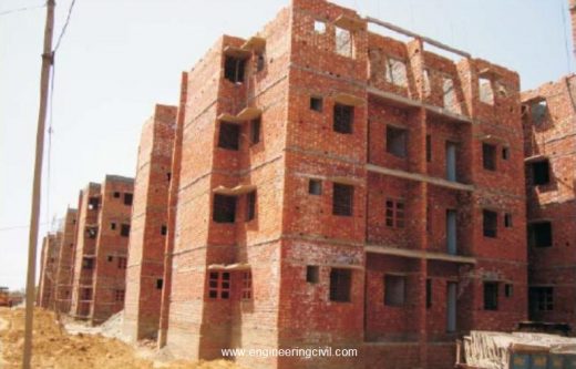
Fig 1: Brick Load Bearing Construction
With natural hazards like earthquake or high speed storms hitting various parts of country more frequently, such load bearing wall construction is no longer safe for withstanding horizontal drifts unless retrofitted. Also such construction is suitable upto G+2 storied building in general.
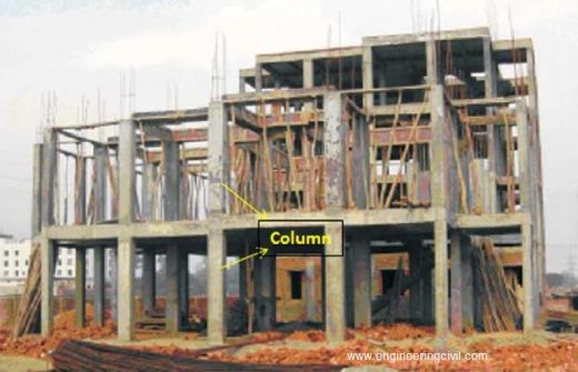
Also as the need of building high storied construction increases, coupled with natural hazards, it is advisable to opt for RCC (Reinforced Cement Concrete) framed construction (Fig 2). Basically, RCC framed construction consists of a series of columns provided suitably in the house which are interconnected by beams to form a frame. These columns transfer the building load to underneath soil through RCC footings.
The frame, starting from the foundation, has to be designed by a structural engineer who would decide upon the mix of concrete to be used, the sizes of columns and beams as well as the reinforcement to be provided therein, depending on the loads to be sustained by the structure.
What is Column?
Column is a vertical compression member which transmits load of the structure to foundations (Fig 2). They are reinforced by means of main longitudinal (vertical) bars to resist compression and/or bending; and transverse steel (closed ties) to resist shearing force (Fig 3).
Typical Loads to be considered for Column Design
(i) Dead Load: Any permanent load acting on the column, e.g. self-weight of column, weight of beam
(ii) Live Load: Any non-permanent or moving load
(iii) Earthquake Load: Depends on the seismic zone where building is located. Higher is the zone, more is the load
(iv) Wind Load: Depends upon the wind speed, height & location of building. Also terrain and adjacent structures play a role in determination of this load
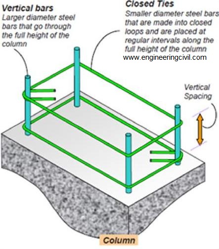
Fig 3
Column Construction: Busting Myth
| S No | Myth | Actual |
| 1 | 4-12 or 4-16 dia may be sufficient for my building of 2/3 storey | Column is the most important structural member to transfer the floor loads coming from each floor. Failure of column can lead to bulging or collapse of whole structure. Depending on plan layout of your building, loads coming and nos of storey, column cross-section and its rebar are determined. There is no standard guideline as such. |
| 2 | 25mm (1 inch) clear cover is sufficient for columns | Clear cover is provided based on durability (exposure) and fire resistance criteria. As per BIS456-2000(b), it is recommended to use min 40 mm cover (approx. 1.5 inch) for columns. However if column section is less than 200 mm and rebar dia 12 mm, then only 25 mm (1 inch) clear cover is possible. |
| 3 | 6 mm rings/ties are too thin to hold the column rebars | Use of 6 mm rings is allowed as per BIS guidelines and makes no difference to the structural stability of column, provided it is made and fixed as per BIS guidelines. It also results in significant savings over 8 mm rings. |
| 4 | Rings can be placed at a standard spacing (150/200 mm c/c) throughout in thecolumn | As per the guidelines of ductile design code for RCC structures BIS 13920, rings should be placed at closer distance (about 3’’ to 4’’) upto L/6 distance [L=unsupported height of column] from any beam- column joint. The spacing in the balance central part of column can be 6’’. |
| 5 | 8 mm or 10 mm rebar as vertical bars of column can be sufficient | It is recommended in BIS456-2000(b) to use min 12mm rebar as column verticals, irrespective of any condition. However, the number of rebar would be decided based on design engineering. |
Recommended construction practices for columns
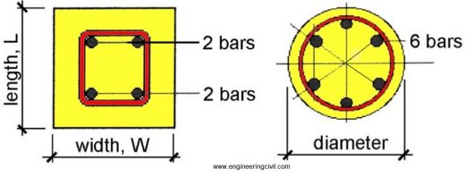
1. A minimum of 4 longitudinal rebars in rectangular and 6 in circular columns should be provided in a column (Fig 4).
2. Rebars should be placed symmetrically across the axes of symmetry (Fig 5). With unsymmetrical reinforcement there is always a danger of smaller amount of steel being wrongly placed on the face requiring the larger reinforcement.
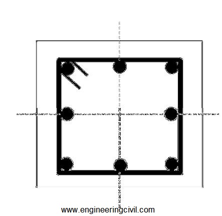
Fig 5
3. If column rebar is to be used for future construction or expansion, it is recommended to apply a coat of cement slurry (cement: water = 1: 3) to the exposed portion of rebars and wrap them with some polythene or jute cloth to prevent direct contact with atmosphere to guard against atmospheric corrosion and therefore loss of material for joining for future constructions.
Note: Cement slurry provides a natural guard against the atmospheric corrosion to protect it.
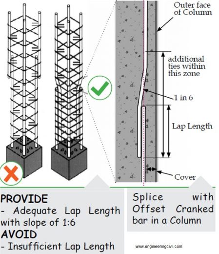
4. While lapping/splices column rebars, it should be ensured that the connecting rebar is given a slope of 1 in 6 (minimum) such that the centre line of both rebar coincides (Fig 6).
5. Lapping should preferably be done in the centre part of column with a min lap length of 57 times the dia of rebar(c). So if you are using 16 mm rebars then lap length will be 3 feet.
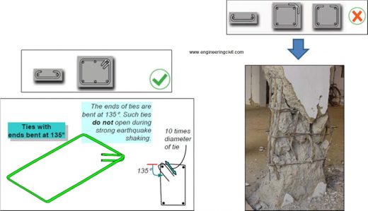
6. The ends of the ties must be bent as 135° hooks. The length of tie beyond the 135° bends must be at least 10 times diameter of steel bar used to make the closed tie; this extension beyond the bend should not be less than 75 mm (Fig 7a).
If this guideline is not followed then the tie/ring holding the vertical rebars have a higher probability of opening up during an event like earthquake. This consequently may lead to failure of column (Fig 7b).
7. Minimum grade of concrete to be used for building a RCC column is M20.
8. Minimum percentage of steel to be used in a RCC column is 0.8% of cross-sectional area of column.
Note on Honeycombing
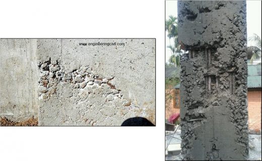
Honeycombs are hollow spaces and cavities left in concrete mass on surface or inside the concrete mass where concrete could not reach. These look like honey bees nest (Fig 8).
Honeycombs which are on sides are visible to naked eyes and can be detected easily as soon shuttering is removed. Honey combs which are inside mass of concrete can only be detected by advanced techniques like ultrasonic pulse velocity testing or rebound hammer test.
Honeycomb is formed mainly due to:
a) Improper vibration/compaction
b) Less cover to reinforcement bars
c) Construction joints (joints upto which a stage of construction is done) are the typical positions where honeycombs are observed. This is due to non-treatment of construction joints (cleaning of laitance and loose cement slurry from joint using wire brush/chipping) before resuming construction.
d) Improper mix proportioning of various components of concrete and/or improper gradation of aggregates are also responsible for such honeycomb formation.
Remedies for Honeycombs in Concrete:
• Strictly speaking wherever honeycombs are observed concrete should be chipped off at that location and the portion should be re-built after applying fresh concrete. Honeycombs as a defect not only reduces the load bearing capacity but water finds an easy way to reinforcement rods and corrosion starts. Corrosion is a process which continues through reinforcement rods even in good concrete, which results in loosing grip between rods and concrete, which is very dangerous to safety and life of concrete structures.
• It will not be out of context to point out that by applying superficial cement plaster on the honeycombs can be a temporary solution of hiding them, but is never safe/advisable.
• At beam-column junction, concrete with 20 mm and below graded aggregates can be used with slightly more water and cement to avoid honeycombs.
• Use of needle vibrator for proper compaction of concrete helps in reducing honey combs. The fresh concrete should be thoroughly vibrated near construction joints so that the mortar from new concrete flows between large aggregates and develops proper bonding with old concrete.
References
(a) BIS 1786 is the BIS code which gives the guidelines pertaining to steel quality for all steel manufacturers to follow
(b) BIS 456-2000 is the BIS code of practice for plain and reinforced concrete structures
(c) Suggestion made considering M20 grade of concrete (cement:sand:graded stonechips=1:1.5:3) and Fe500 grade of HYSD rebar
We at engineeringcivil.com are thankful to Er. Sourav Dutta for submitting this paper to us. We hope this paper will be helpful for the whole construction industry in general.
If you have a query, you can ask a question here.


Warm regards for Er. Sourav Dutta for nicely presenting the significant points for sound construction practice.
Also http://www.engineeringcivil.com effort for presenting the article is well appreciated.
Stay Blessed.
It is my privelege to be a part like a small droplet of great Civil Engineering discipline , by following engineeringcivil.com
using of isbm 150×75 in place of tmt bars
Thanks a lot for your detailed write up.
Need help wrt to column tmt bars cranked, 8328381259 is my contact please share your contact no